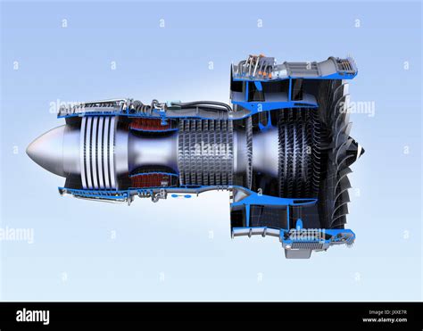
The jet engine is a marvel of modern engineering, with its complex systems and components working together in harmony to produce the thrust needed to power modern aircraft. One of the most fascinating aspects of jet engine design is the cross-sectional view, which reveals the intricate details of the engine's internal workings. In this article, we will delve into the world of jet engine cross sections, exploring the various components, their functions, and the importance of their design.
A typical jet engine consists of several major components, including the compressor, combustion chamber, turbine, and nozzle. The compressor, which is responsible for drawing in air and compressing it, is typically located at the front of the engine. The compressed air is then mixed with fuel in the combustion chamber, where it is ignited, producing a high-temperature and high-pressure gas. This gas then expands through the turbine, which extracts energy from the gas to drive the compressor and other engine components. Finally, the gas is expelled through the nozzle, which accelerates the gas to produce the thrust needed to propel the aircraft.
Key Points
- The compressor is responsible for drawing in air and compressing it, with a typical compression ratio of 10:1 to 20:1.
- The combustion chamber, also known as the burner, is where the compressed air is mixed with fuel and ignited, producing a high-temperature and high-pressure gas.
- The turbine extracts energy from the gas to drive the compressor and other engine components, with a typical turbine inlet temperature of 1,000°C to 1,500°C.
- The nozzle accelerates the gas to produce the thrust needed to propel the aircraft, with a typical exhaust velocity of 500 m/s to 1,000 m/s.
- Modern jet engines typically have a bypass ratio of 5:1 to 10:1, which means that for every 1 kg of air that passes through the core engine, 5-10 kg of air bypass the core and are accelerated by the fan.
Compressor Section

The compressor section of a jet engine is responsible for drawing in air and compressing it to the high pressures required for combustion. The compressor typically consists of multiple stages of rotating blades, which are driven by the turbine. Each stage of the compressor consists of a rotor and a stator, with the rotor blades accelerating the air and the stator blades diffusing the air to increase its pressure. The compressor is typically divided into two sections: the low-pressure compressor (LPC) and the high-pressure compressor (HPC). The LPC is responsible for compressing the air to a pressure of around 5-10 bar, while the HPC compresses the air to a pressure of around 20-50 bar.
Compressor Blade Design
The design of the compressor blades is critical to the performance of the engine. The blades must be designed to withstand the high stresses and temperatures associated with compressing air to such high pressures. The blades are typically made from high-strength, high-temperature materials such as titanium or steel, and are designed with a complex curved shape to maximize their efficiency. The blades are also coated with a thin layer of material to reduce friction and prevent wear.
| Compressor Stage | Pressure Ratio | Temperature Increase |
|---|---|---|
| LPC | 1.5:1 to 3:1 | 50°C to 100°C |
| HPC | 5:1 to 10:1 | 100°C to 200°C |

Combustion Chamber Section

The combustion chamber, also known as the burner, is where the compressed air is mixed with fuel and ignited, producing a high-temperature and high-pressure gas. The combustion chamber is typically a cylindrical or annular shape, with a series of fuel injectors and igniter plugs. The fuel injectors spray fuel into the combustion chamber, where it is mixed with the compressed air and ignited by the igniter plugs. The combustion chamber is designed to withstand the high temperatures and pressures associated with combustion, and is typically made from high-temperature, high-strength materials such as ceramic or refractory metal.
Fuel Injection System
The fuel injection system is a critical component of the combustion chamber, as it provides the fuel required for combustion. The fuel injection system typically consists of a series of fuel injectors, which spray fuel into the combustion chamber. The fuel injectors are designed to provide a precise amount of fuel, and are typically controlled by a complex system of sensors and actuators. The fuel injection system must be designed to withstand the high temperatures and pressures associated with combustion, and must be able to provide a consistent and reliable flow of fuel.
| Fuel Injector Type | Fuel Flow Rate | Ignition Energy |
|---|---|---|
| Pressure Jet | 10 kg/h to 50 kg/h | 10 J to 50 J |
| Air Blast | 50 kg/h to 100 kg/h | 50 J to 100 J |
What is the purpose of the combustion chamber in a jet engine?
+The combustion chamber is where the compressed air is mixed with fuel and ignited, producing a high-temperature and high-pressure gas.
What is the typical temperature increase in the combustion chamber?
+The typical temperature increase in the combustion chamber is around 1,000°C to 1,500°C.
What is the purpose of the fuel injection system in a jet engine?
+The fuel injection system provides the fuel required for combustion, and must be designed to withstand the high temperatures and pressures associated with combustion.
In conclusion, the jet engine cross section is a complex and fascinating topic, revealing the intricate details of the engine’s internal workings. The compressor, combustion chamber, turbine, and nozzle all work together to produce the thrust needed to power modern aircraft. By understanding the design and function of these components, we can appreciate the incredible engineering that goes into creating these powerful machines.